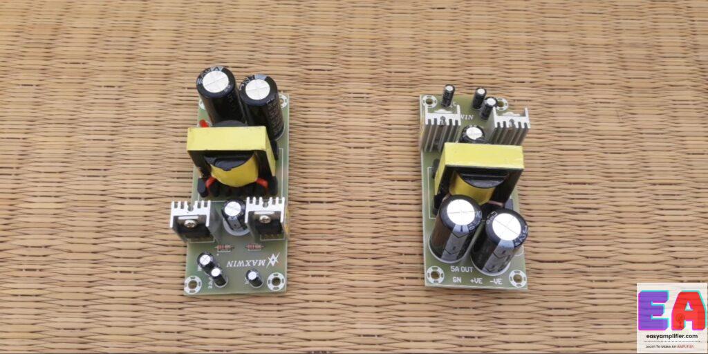
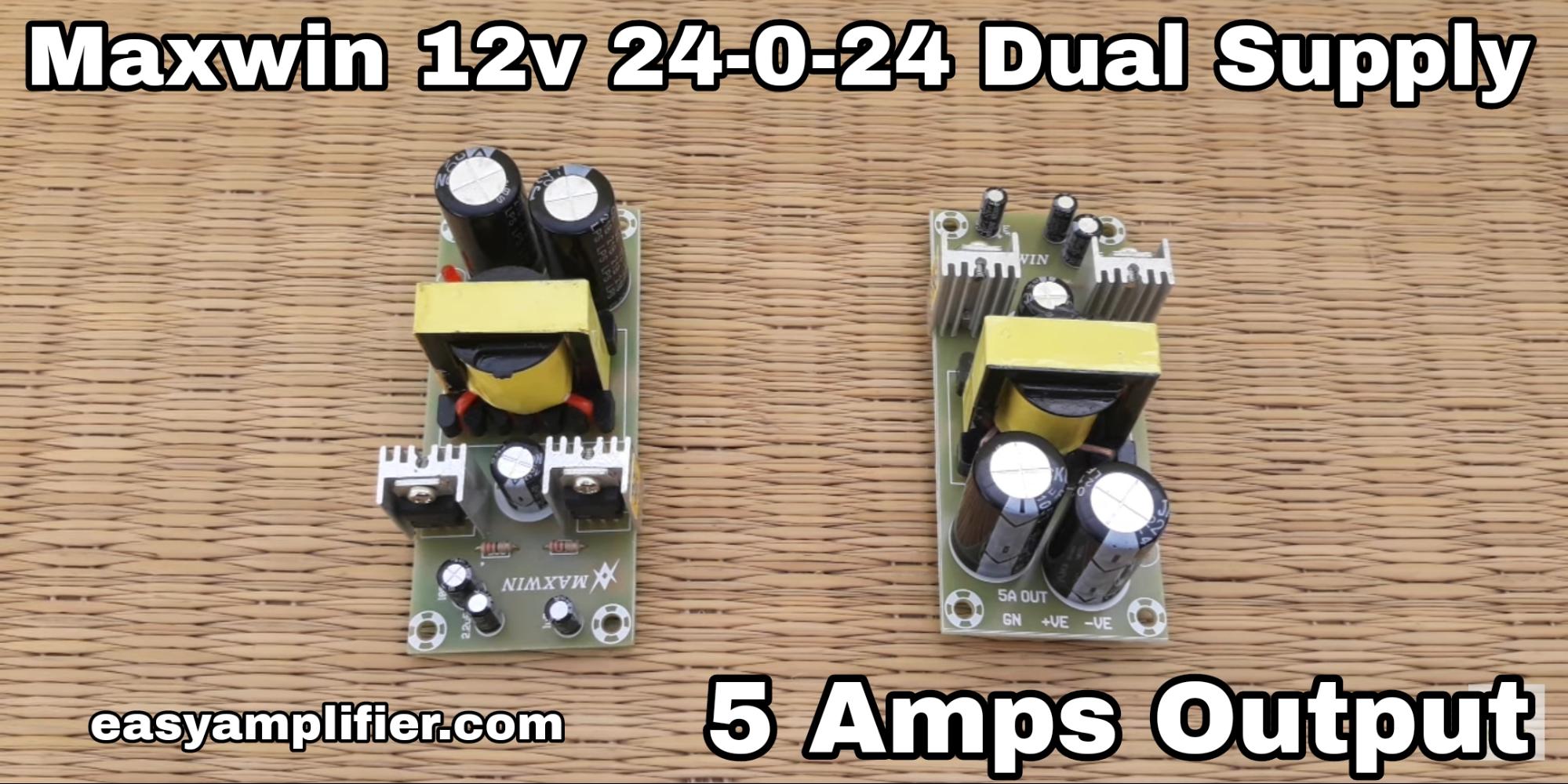
Hi music lovers today in this article we are going to read about Maxwin 12v to 24 0 24 converter circuit diagram board Review and input and output connection details
Table of Contents

What is a 12v to 24v converter board?
Whenever you assemble an amplifier for the home you can quickly Assemble it by Using a transformer and getting the dual power supply from the transformer And use it. But If you want to assemble an amplifier for an Auto, van, or truck we can’t assemble it because The battery voltage range is Limited to 12v. So that’s why we use this board because This board can convert your battery 12v into a Dual power supply of 24-0-24 5 amps. So you can Easily assemble a stereo or 2.1 amplifiers The Home amplifiers.
Where to use this board?
If you want to assemble a High-quality Stereo or 2.1 amplifiers, use this converter board to get the best result. Because this converter board Will Give you 24-0-24 with 5 Amps Power output, you can Assemble any type of amplifier With the help of this converter board for example you can assemble Two fET stereo amplifiers, STK 4141, 4191, 4231, and Tda7265 Or you can Use 4440 Ic board For stereo Speakers and 4 FET Mono or stereo Board for the subwoofer. By using this board you can assemble a Good Quality And High Watts amplifier with a low budget.
This converter board comes in Two variants which are LD ( low density), and HD (high density). In the LD converter The output current ampere range is only 5 amps. But In the HD converter, You can Get from 10 amperes to up to 30 amperes.
Connection details maxwin 12v to 24 0 24 converter board

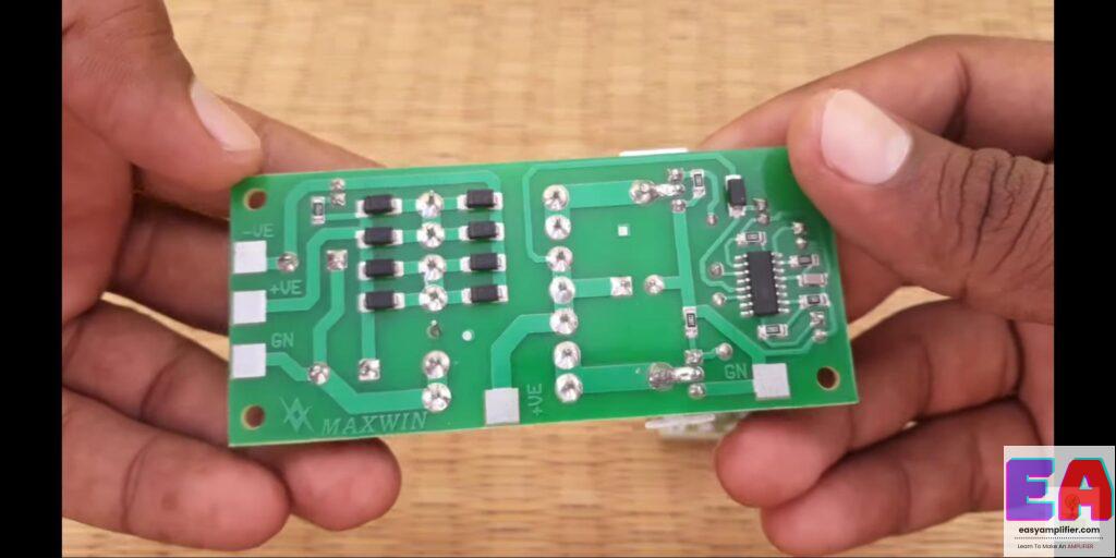
In this board, They use good quality components so you can get the perfect Voltage and amperes From this board. All the connections are Mentioned on the product PCB. Always use good quality wires for the power supply section for example Use 1.5 to 2.5 Square mm Wires to get the perfect Power output from this board without ampere losses.
So that’s all friends about this maxwin 12v to 24 0 24 converter board small article if you like this article please share it with your friends.
12v to 24 0 24 converter circuit diagram

This is an image that will help you to understand the circuit, now by seeing this image you will know which thing to put where 12v Dc To 24 0 24v Converter Power Supply Circuit Must see the image, this PDF to download 3D image download
Friends, have found that how to make our 12v Dc To 24 0 24v Converter Power Supply Circuit, you must have understood this post, if you have any problem then definitely comment to us 24/7 we will help you here because I did not show the image so that Thank you for reading this poster of ours to see better in pdf.
Parts Required to Make 12v to 24 0 24 converter circuit diagram
By using this converter power supply circuit I Register (7), Pf(6), Capacitor (4), Diode (5), Ic 3525 (1), DT Chok (1), and Mosfet (2) we get 12v Dc To 24 0 Can Create 24v Converter Power Supply Circuit
- Ragister : 46ohm, 26k, 100ohm , 12k (2) 12ohm (2)
- PF : 102(2) और 104 (4)
- Diode: 4007 (1) 5408 (4)
- Copacitor : 50v 4.7uf (1) 25v 2200uf (1) 35v 2200uf (2)
- DT (chok 1) Ic 3535 और IRFZ44 Mosfet (2)
And this board is available for sale from me. You can buy this board by asking me in the comment section or you can Ask me on Facebook or WhatsApp bye friends.

